Range of Light Photography | Range of Light Photography™ | Techniques | A Darkroom Portrait
A Darkroom Portrait
Table of Contents
THE FREEDOM TO DO YOUR OWN THING
Sooner or later every photographic artist concerned about the quality of their work, their own personal vision, and the freedom to execute either, will have to face the challenge of building their own workspace, designed to service their needs alone. This task becomes increasingly problematic as darkroom equipment manufacturers disappear from the marketplace, and digital "lightrooms" become the norm. What follows is a basic working darkroom designed to serve my particular requirements. It is by necessity, a compromise between my needs and my desires. It could be perfect, given unlimited space and money - of which I have neither.
Basic darkroom plans and construction techniques may be found in Build Your Own Home Dark-Room and The New Darkroom Handbook. My darkroom (aka, the lab) is based on a classic wet side/dry side plan.
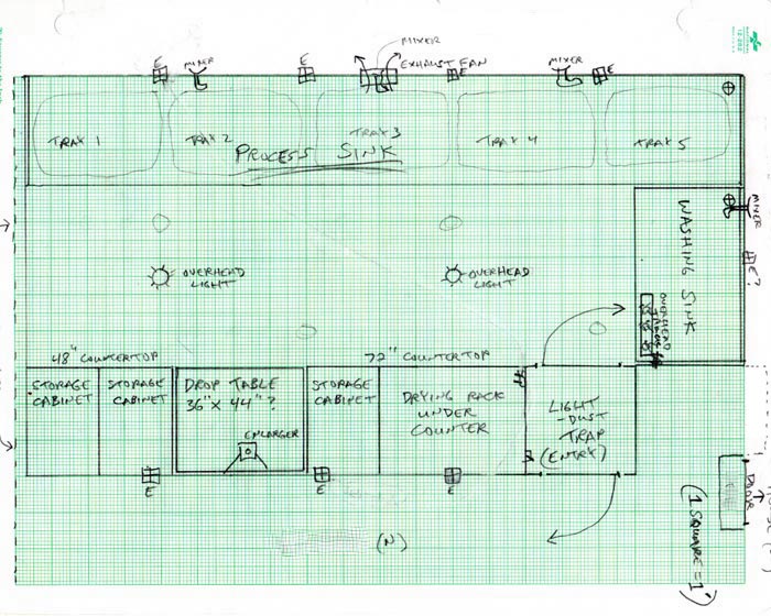
My most basic criteria of building a darkroom was to build a light proof box (the ceiling and walls) around a sink large enough to produce fine art prints up to 30"X40". Simple. That's right, for my purposes, it really was all about the sink. Everything else was subservient to this goal. Attendant to the minimum required sink dimensions (~20 feet long by 371/2 inches wide by 8 inches deep), was sufficient ceiling height to both expose and handle large sheets of paper. My "box" is 20 feet long by 11 feet wide by 9 feet high. A 9 foot ceiling and a 48 inch drop table allows me to work with a vertically oriented wall mounted enlarger, and still gives me the ability to crop any size negative from 35mm to large formats, resulting in my largest desired print. The workflow loops clockwise beginning at the enlarger, proceeding along the process sink to the wash sink and on to the print drying screens under the counter next to the enlarger. Here, is my original FLOOR PLAN drawing, from which I deviated little during actual construction:
Virtually all construction material was obtained from your garden variety home big box hardware stores. Standard 2X4 and sheetrock "stick" construction was employed throughout. Greenboard was used on the walls behind the sink, but given how humid and wet the lab can become, I now feel that greenboard should have been used exclusively in place of sheetrock. A semi-enamel style flat white paint is used throughout, assisting in reflecting the single safelight into the farthest parts of the room, and creating a more pleasant atmosphere at other times. Quad-style electrical outlets are installed throughout the lab and above the sink, with one outlet on each wired to a wall switch near the door. A separate electrical panel serves only the lab. I ultimately tripled the number of 75 watt "downcan" overhead lights (aka, house lights), shown in the FLOOR PLAN from 2 to 6.
Since all photographic processes are temperature sensitive, some kind of air conditioning is desirable in order to work year-round. This is perhaps not so critical with monochrome materials and processes (my specialty) as it is with color, but one thing's for sure, I am temperature sensitive. I opted for a mini-split, ductless heat pump system that easily and swiftly heats and cools the insulated room to a proper operating temperature of 20°C (68°F). Such temperature mitigation is not only required for consistency of method and result, but many enlargers will not operate optimally in extremes of hot and cold.
Entry into the lab is serviced by two inexpensive light sealed hollow core doors through a light/dust trap, 3 feet square. Installing a light trap allows one to enter and leave while light sensitive material is exposed, as necessary. A light proof vent was installed in the outer door to ease air pressure created by the two tightly sealed door jambs. Notice that a major safety item was not incorporated into the plan. A so-called "panic" door, allowing alternate egress in case of emergency, was impossible to build into the particular space. I recommend one.
Task lighting, while not an afterthought, was left as an option once the room was completed, because of inevitable changes being made during construction. The concession to hardwiring specific lighting locations likely to change during actual use, was to install special electrical outlets located in the ceiling above the sinks (3 above the process sink and 1 above the wash sink) controlled solely by a footswitch (sourced through Grainger) located on the floor in front of the sink. Plug in track lighting, purchased on sale at the home store, was installed on the ceiling at the footswitched outlets, at any location within the entire room. The footswitch enables me to turn on the track lights with wet hands and while holding prints during processing and to direct spot lighting to the print inspection area at the sink. Spots are also directed across the room to easels holding finished prints, as well as the WASH SINK. Fact is, I only use the ceiling mounted house lights upon entering or leaving the lab. The track lights are used almost exclusively when working (they also impart a nicer ambience as well). The task lighting consists of 75 watt daylight-balanced halogen spots. These home store fixtures are being replaced with low-voltage gallery quality spots (Solux 3500K - 35 watt) as needed.

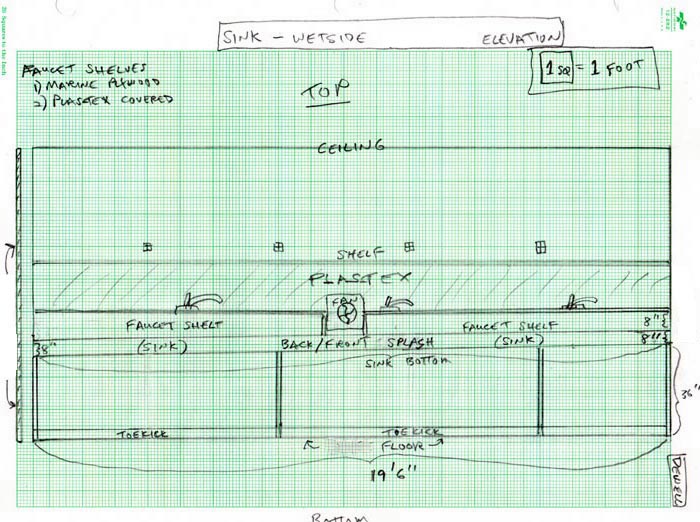
Above is an oblique view into the far end of the long sink wall (taken from the door). As can be seen from the FLOOR PLAN and SINKS PLAN, my process sink is built wall-to-wall-to-wall, occupying the entire length of one wall, end to end. It is constructed of 3/4 inch marine-grade plywood with an 8 inch splash surround. Marine-grade plywood is expensive (compared to construction grades) but the glue used in its laminations will not dissolve when it gets wet. I used Gel-Coat to "waterproof" the sink. The sink is essentially a 20 foot boat designed to keep water in. As many other waterproofing methods are available, I do not recommend Gel-Coat as it is difficult to work with (unless you're already a boat builder) and the fumes are extremely toxic. The sink is not designed to hold water (though this sink is built so strongly that it easily can) but rather to hold trays of various sizes containing processing chemicals. It is supported by the wall (studs) at the back and ends, as well as 2x4's every 4 feet along the front.
Hot and cold unfiltered water is delivered to 3 locations along the wall through standard single lever mixer faucets ($5 closeouts at the home center). I attached inexpensive coil hoses with sprayers to each faucet and suspended them from ceiling hooks to allow water to reach all locations of the sink without hoses obstructing the work area.
The base sink height varies from 29 to 34 inches and is pitched a quarter of an inch per foot both lengthwise and widthwise towards a single corner drain located at the rear. I must constantly keep on top of rinsing it clean with the sprayers as I work, though no amount of diligence seems to prevent pyro (developer) and selenium toner from staining it. To facilitate drainage, the trays do not sit directly upon the sink bottom, but are supported by restaurant style porous floor tiles at each corner. Both vertical and horizontal tray storage (for mural sizes) occupies much of the under sink area. My "medium" size Cesco trays, sufficient for all prints up to 20"X24", are visible in the photo. Splash panels, made of poylethylene sheeting of the type seen in restrooms and commercial kitchens - turned smooth side out, surround the sink to 4 feet to prevent water from wetting the walls. The process sink dimensions are based on my height of 6'1" (swoon) and the desire to print big.
A single large Doran light-baffled exhaust fan is installed centrally above the process sink. It is spec'd to more than handle the air volume of the room (i.e., 20'L X 11'W X 9'H ~ 2000 cubic feet). There is an admitted sparseness to the lab in that there is little over sink storage. I used standard movable coated wire shelf racks on vertical tracks which can be placed high enough on the wall to accommodate the extra height requirements for the processing of mural sized prints. An unplanned bonus is that the front rail of the racks makes an excellent way to securely hang sheet (large format) film to dry. A large, drug store variety, battery operated clock with sweep second hand and simple bi-metal temperature and humidity dials allows me to time non-critical print processing events, monitor the lab's general atmosphere, and make it out in time for lunch.
There are few perks in the lab, as I like to keep things simple (and must keep them cheap). I tray process sheet film, and use standard stainless steel Hewes tanks and reels for developing roll film. One splurge is the Zone VI temperature compensating timer, which expedites and ensures consistent developing of both paper and film. Incidentally, the stool only gets brief use, primarily during the development cycle.
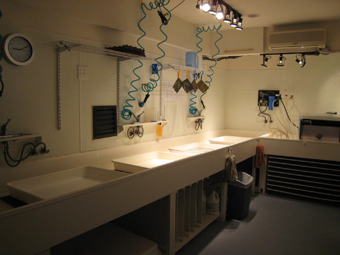
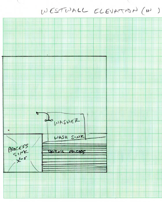
Looking down the long sink towards the door end of the lab, the air-handling half of the mini-split heat pump (split, because the condensing unit is located outside the room) can be seen on the end wall over - guess what - another sink! The WASH SINK is a separately drained unit from the process sink. It snugly contains a roll film washer, 16X20 flat holding wash, 16X20 vertical slot Cachet EcoWash, and 20X24 Calumet (GravityWorks) opposing jet style vertical slot washer.
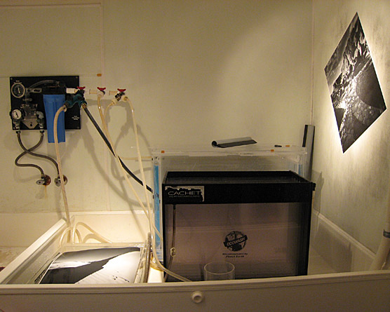
I briefly mention here, just why I have so many washers when one large one would serve many purposes. In the mid 2000's many larger photo stores (i.e., Samys, Freestyle, etc.) began closing down or radically downsizing their darkroom departments. The result was a cornucopia of deeply discounted lab items and overstocked papers, most well below cost. It seemed penny smart and dollar foolish not to invest in anything darkroom related, even without a specific need at the time.
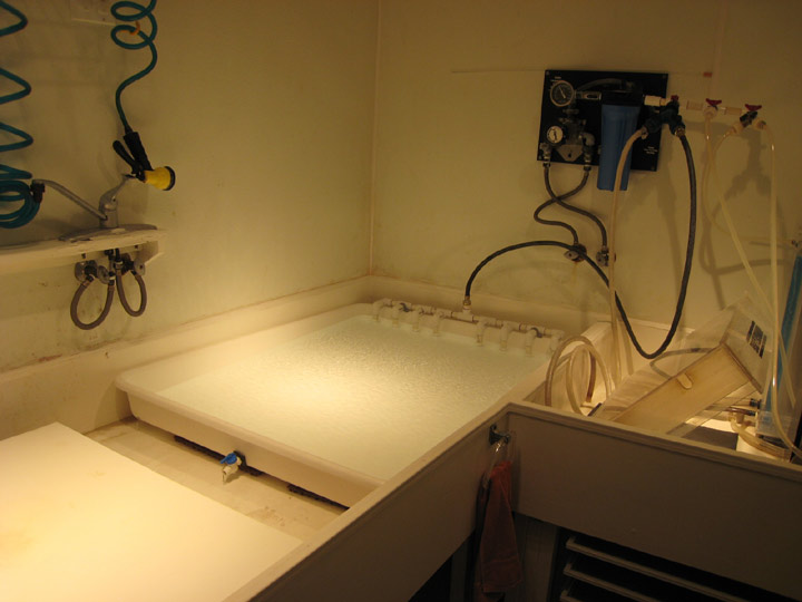
Remember the poly sheeting lining the walls above the sink, smooth side out? Here, on the adjacent wall, is where I squeegee washed prints (non-emulsion side only) before drying. Beneath the sink are auxiliary print drying screens.
A temperature regulated water panel is located over the junction of the process and wash sinks. A good water control panel is a requirement to produce results of consistent quality. Mine is a relatively inexpensive Delta 1 unit that has served well for many years. I have constructed a multi-outlet manifold made of glued-up lawn irrigation fittings off the control unit which serves individual washers as well as a free hose. I have retrofitted one of my largest trays with a manifold and jet arrangement to provide an active wash for mural sized prints.
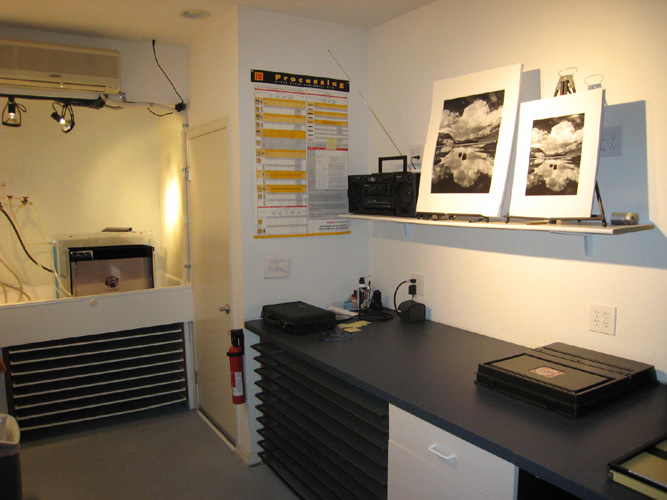
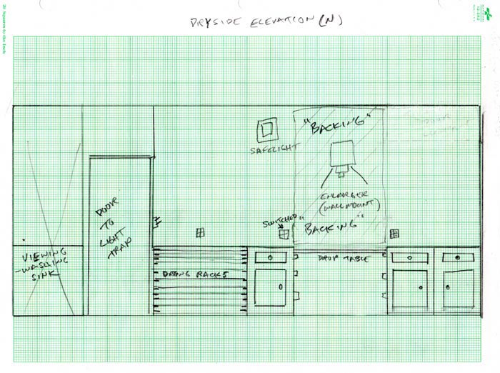
The dry side was constructed with home store, sale purchased, garage-style melamine cabinets supporting formica laminated particle board shelving, 3 feet deep, running the length of the wall from door to room's end. Immediately adjacent to the door, beneath the shelf are the 10 main print drying screens, stacked 3 inches apart, large enough to dry my largest prints with ease. These nylon screens were ordered locally from a screen maker, using the exact dimensions of the install space between the door and the first cabinet. They slide in and out and are supported by aluminum 'c'-channel at the sides.
The dry-side shelf-desk holds my lightbox and loupe, where I prepare negatives, hold the day's paper, and make notes. A small shelf above, which folds down when not in use, holds a radio/boombox and two small easels for print matching when doing editions. I normally have two paper safes when printing up to 16X20 - one for unexposed paper to the left of the drop table and one on the right side for exposed paper, conforming to the aforementioned clockwise workflow. Once I have a fine print, I can expose any number of sheets in succession, and then process two to four at a time (depending on size) until all are in the final water holding bath.
Just inside the door, on the wall below the Kodak Film Development Poster, are the electrical switches for the room. One controls the house lights (ceiling cans), one the switched outlets, and one is a variable speed controller for the exhaust fan. Completing the other half of the fresh air system, unseen in the ceiling above the corner of the shelf, is a small filtered register with a 10 inch duct running to the outside. It permits a passive flow of air, pulled through the room actively when the exhaust fan is running over the sink on the wet side. Room light switches have also been installed inside the light trap.
Note the fire extinguisher mounted by the door. While no exposed flames are used within the lab, one never knows with certainty when an electrical short may occur, or a fire from outside may reach the isolation of this quiet retreat. With only one door for entry and egress, it is wise to include some sort of fire safety equipment, to fight your way out, if necessary. Ceiling mounted smoke alarms (with blacked-out LED lights) are located on both sides of the light trap. As it might be difficult to find the door during a power outage, I affixed theatre style glow tape to the door handle (and tracklight footswitch). Initially, I applied the tape liberally throughout the lab. It turned out to be quite bright when all the lights were turned off during film processing - too much so for my peace of mind. I removed all of it except that on the door handle. Even now, I usually throw my shirt over the handle to cover the tape when I load film holders or tray process film (Doesn't everyone work in their lab starkers - just how did you think I accomplished those "third hand" dodges under the enlarger?). I also have a working flashlight available for any such emergency. A cordless phone sitting on the shelf is hidden in a drawer when developing film.
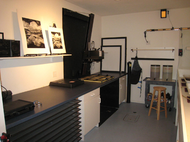
The enlarger site is between the first cabinet and the cabinet at the end of the wall. During construction of the walls, a shear wall of 3/4 inch plywood was inserted behind the sheetrock to provide a stable and rigid mount for an oversize wall-mounted enlarging column. The whole site has been painted flat black to prevent errant reflections from light sources during print exposures - though I have no evidence that this is strictly necessary with my particular enlarger. A four foot section of laminated shelf was cut from the original and serves as a drop table, supported by racks at three heights built into the sides of the bookended cabinets. This simple arrangement allows vertical enlarging to my maximum desired sizes by increasing enlarging distance without (or in combination with) raising the enlarger head. As seen in the final photo, it is flush with the entire shelf in its normal working configuration (i.e., sheet sizes). I use a Zone VI 5X7 cold light enlarger with a Metrolux II timer and footswitch for negatives from 35mm (rarely) to 5X7 large format. Visible on the drop table is the Saunders 20X24 four-bladed easel I use for all sheet paper as well my two homemade mural-size easels standing upon the shelf, leaning against the far wall. The drawers and cupboards of the cabinets hold enlarging lenses, lens boards, negative carriers, burn cards, paper safes, grain focuser, Parallel alignment tool, etc.
At the far end of the lab is my homemade roll paper holder and ABS pipe "light safe", chemical cart, and safelight. Note that the safelight was moved from its location in the DRY SIDE ELEVATION PLAN to the end wall of the lab, where it provides more even lighting. The safelight is plugged into one of the switched outlets, controlled from the switches near the door. The unknown final positioning of the safelight was the primary reason for assigning one of the quad outlets at each location to switchable status. The Zone VI DuoSafe light was another splurge, justified by its low operating cost, extremely long life, and variable light intensity. While a very bright and cheery "graded" setting can be used for most paper exposures and processing, a much dimmer "variable contrast" may be employed for exposures longer than say 20 minutes - VC or graded (practically, only necessary on some murals).
While not ideal, the whole thing works pretty well, given my specific needs, artistic goals, limitations of space, money, and time. I hope this tour of my "sacred space" will help you to realize yours.





4 个留言
Alejandro Mora: on 二月, 2012
As I'm researching in order to build my very first real darkroom (I don't count my brief experience with one in my small bathroom) I stumbled upon your great site. I love your setup and before even seeing yours, my sketches seem very similar.
I have many questions I could ask you but my main one is regarding the sink. I too plan on making mine out of Marine grade plywood but I can only find it in 8' planks. I therefore assume you joined a few pieces together to make your drool-worthy sink. Can you tell me how you did this and if you have any tips? I wanted to make mine about 11' - 12' long to comfortably print up to 16x20 but perhaps someday going to even 20x24. Since you don't recommend Gel-Coat, what would you recommend? I was thinking several coats of an epoxy paint.
Thank you very much in advance, and for creating such an instructional site!
Alejandro
Alejandro Mora
Ben: on 二月, 2012
You are quite right that plywood, marine grade or otherwise, is basically available in standard 8 foot sheets. My sink is pieced together in 8 foot (or shorter) sections, with silicone caulked seams. The bottom "floor" of the sink is joined by screwing the floor sections together with 2X2's running along the seam under the sink, and at every two feet for extra strength. Remember that my process sink is built wall to wall to wall, running the full length of the lab, and so is unusually stable – almost like a built in shelf, hanging from the walls and supported by 2X4 struts. Silicone was used to fill screw hole countersinks and other voids, and then sanded smooth. To ease drainage, the sink should rake towards your drain at about one quarter inch per foot.
I don't recommend Gel–Coat, unless you are already proficient in its use. Most home built sinks typically use marine epoxy (hardware, boating stores), or straight epoxy resins. Epoxy itself, can result in quite an ugly sink, but the beauty only needs to be evident in your prints! There are probably other waterproofing solutions available these days at the home stores, such as resin based garage floor sealers, which may be easier to apply and just as durable. It may be worth experimenting with some of these newer options, on a smaller sink such as yours. In order to ease the flow of water and chemicals, the surface should be as smooth and durable as possible.
Thanks for the praise. The ability to help others in their pursuits and the occasional "attaboy" are all I need to keep publishing these articles. :)
Alejandro: on 二月, 2012
jim werner: on 一月, 2013
THX and BTW your work is wonderful
jim werner
Jim,
One needs to align the enlarger head with the printing paper on the baseboard (or easel) every time a new enlargement occurs, if all parts of the print are to remain in sharp focus. This is true with all printing positions, either with wall mounts or enlarger columns attached to baseboards. There are tools available to achieve proper alignment. An important consideration is that your enlarger head be adjustable, in order to achieve a good parallel projection from the negative stage and lens to the paper. When I installed my wall-mounted enlarger, I simply made certain the head was generally level to the "drop table" baseboard. All subsequent adjustments are performed at the 3 point adjustable enlarger head with the aid of a laser alignment tool on the easel (baseboard). I always print with the use of an easel, never directly upon the baseboard, although that is certainly possible. It is also worth noting that no enlarging head will likely maintain adequate alignment (to the paper) as it travels up and down its column, attached baseboard or not.
加入留言:
订阅留言